If ongoing emergency lighting testing, maintenance and record keeping is taking up a lot of your time, you may want to consider installing an automatic testing system.
Watch the video
In most cases ATS (Automatic Testing Systems) are wired systems, or, wireless systems that involve commitment to a single brand of emergency lighting.
At Safecility, we’ve designed a wireless retrofit sensor that can turn any brand of existing emergency light into a “smart light”. So you can switch from manual testing to automatic, without a full lighting upgrade. Safecility works with any DALI enabled emergency light, so if your lighting is not DALI enabled, a DALI inverter can be easily installed at the same time as the Safecility control sensor.
The Safecility Emergency Lighting Control Sensor is connected to the Cloud platform before you receive it. Once you have the Safecility sensor, all you have to do is follow 4 simple installation steps and be up and running with a stress-free wireless ATS system.
Sensor Details
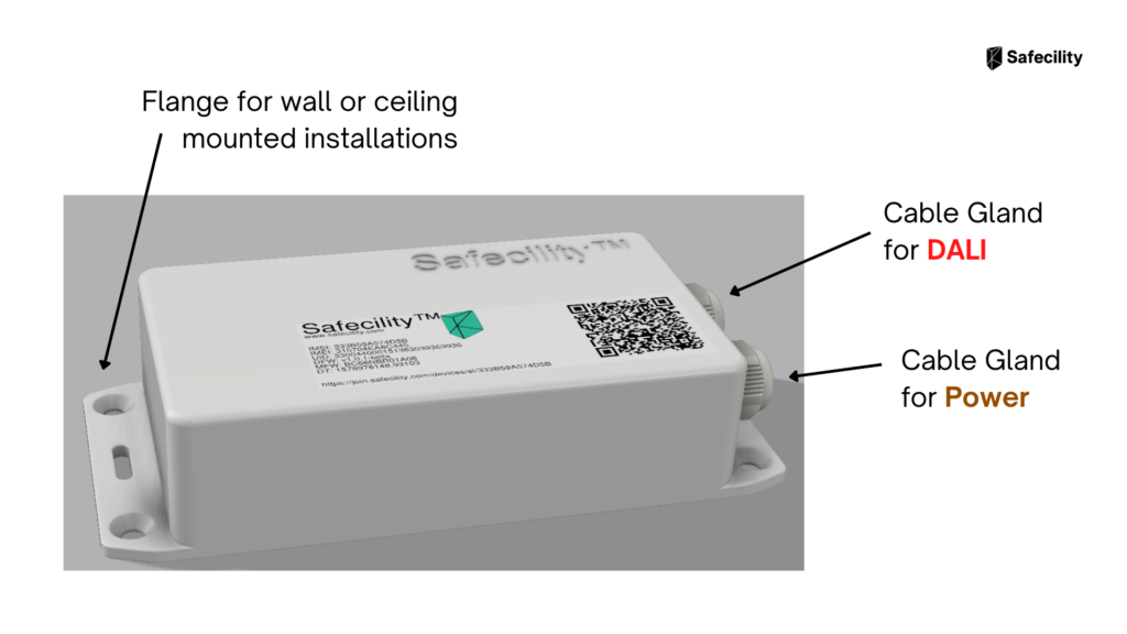
Dimensions: 100x50x20mm
Sensor Casing: Flanged IP54 with x2 cable glands
Weight: 0.1 KG
Commissioning: Sensors are pre-commissioned by Safecility’s technical team prior to delivery.
Before you get started
Before you begin, you’ll need a 3mm flat head screwdriver, wire stripper and a voltage tester. Depending on the model of emergency light, you may need additional tools to remove the cover from the light to access the inside of the light.
Step 1
Ensure that the power has been cut to the circuit that the Emergency Light is on. Confirm the absence of live voltage using your voltage tester. You must ensure that power will not be resorted to the circuit while you are installing the sensor, installation takes roughly 10 minutes.
Step 2
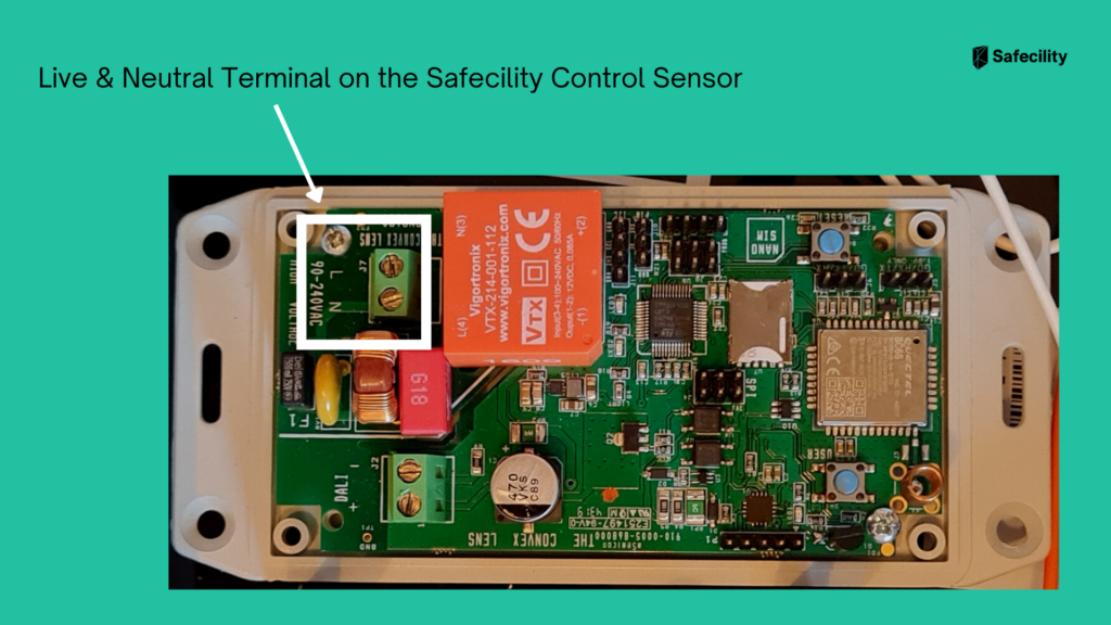
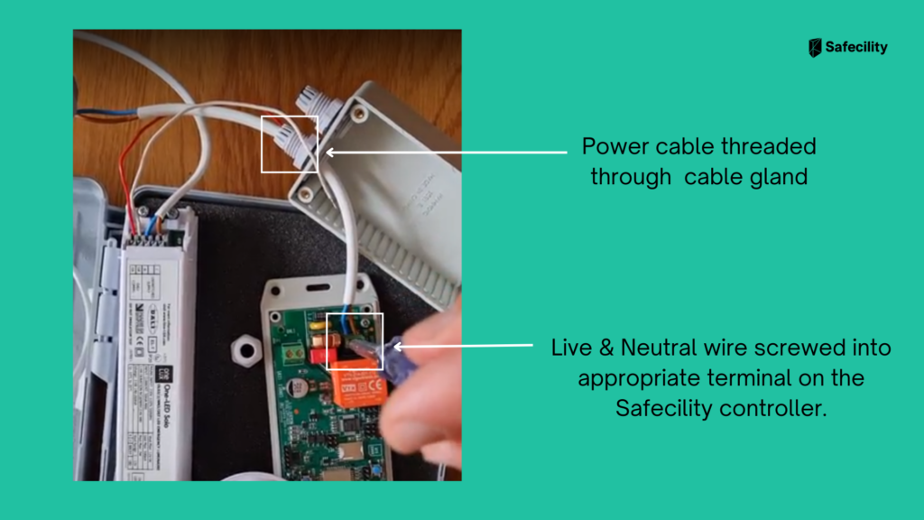
The Safecility control sensor is powered by the same power source that supplies the Emergency Light. The 2 core power cable from the luminaire is run through the gland on the device marked Permanent L/N.
Trim excess length off the power cable and strip the insulation on the live and neutral wires back by approximately 2cm. Match up the live and neutral cables to the appropriate Live/Neutral terminals marked on the Safecility controller and screw into place using your 3mm flat head screwdriver.
Step 3
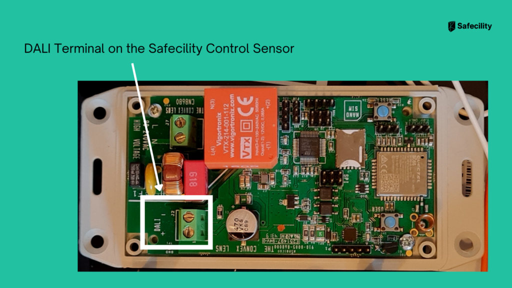
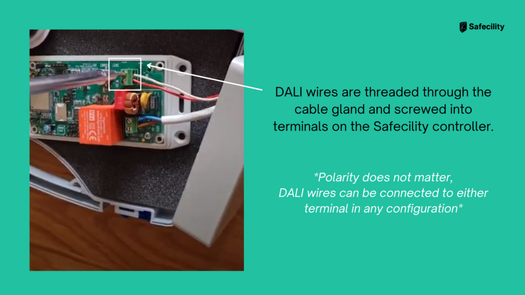
Next the DALI Inverter is connected to the Safecility control sensor. The 2 core DALI cable from the DALI inverter is run through the gland on the device marked DALI.
Trim excess length off cable and strip the insulation on the wires back by approximately 2cm. The wires are then connected to the DALI terminals on the Safecility controller and screwed into place.
NOTE: Polarity is irrelevant so DALI 2-core wire can be connected to the Safecility terminals anyway you choose.
Step 4
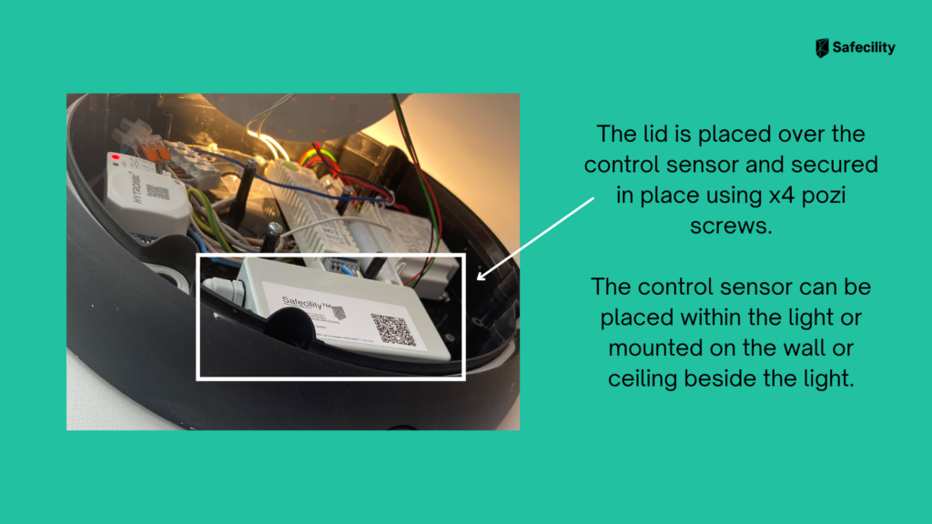
Now that the cables have been terminated, install the lid with 4 pozi-drive screws provided. The controller can be fixed in position, using either double sided tape on the reverse side of the enclosure or by drilling into the mounting surface, installing rawl plugs and screwing self-tapping screws through the flanges.
Once you are satisfied with the installation, you can now restore power to the circuit.
We hope this guide will help you when installing Safecility Emergency Lighting Control Sensors. If you’d like to view technical detail about the sensor, you can download the spec sheet here.
If you liked this article, then please follow us on Linkedin for more guides, updates and emergency lighting news. You can also find us on Twitter and Facebook.
We’re here to help
If you have any installation questions get in touch today.
Email: [email protected]
Phone: +44 7908 070158

